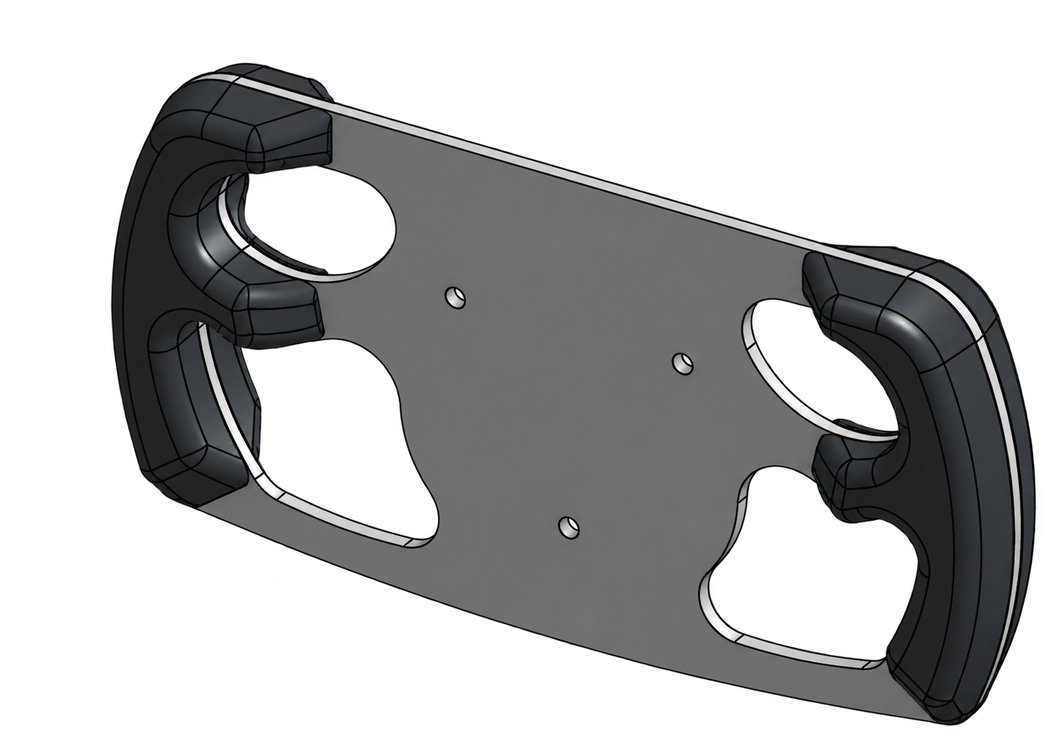
Design Challenge
How can I remove unnecessary material without compromising strength, stiffness, ergonomics, manufacturability, or Formula SAE rule compliance?
Structural integrity
Maintain a simulated yield FOS ≥ 2 under the study’s assumed extreme driver loads.
Low mass
Remove material that contributes inefficiently to the load path.
Driver ergonomics
Gloved operation, finger clearance, and neutral grip position.
Rule compliance
Continuous, non-concave perimeter and accessible quick disconnect.
Manufacturability
Primarily planar aluminum architecture compatible with team fabrication resources.
Serviceability
Replaceable grips and accessible, inspectable hardware.
Architecture Selection
I compared three architectures with a weighted decision matrix before developing the structural CAD.
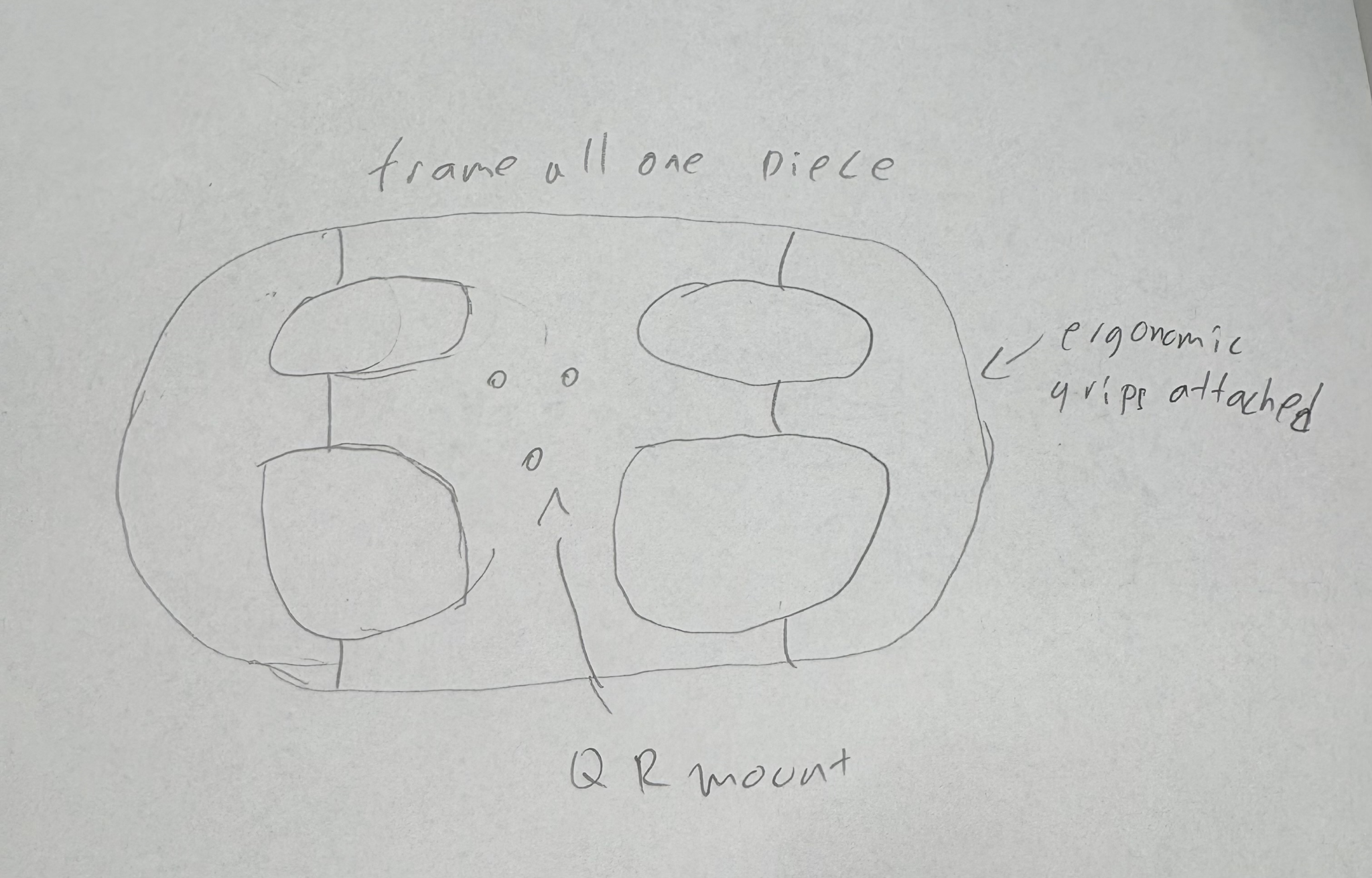
One-Piece Closed Frame
4.65 / 5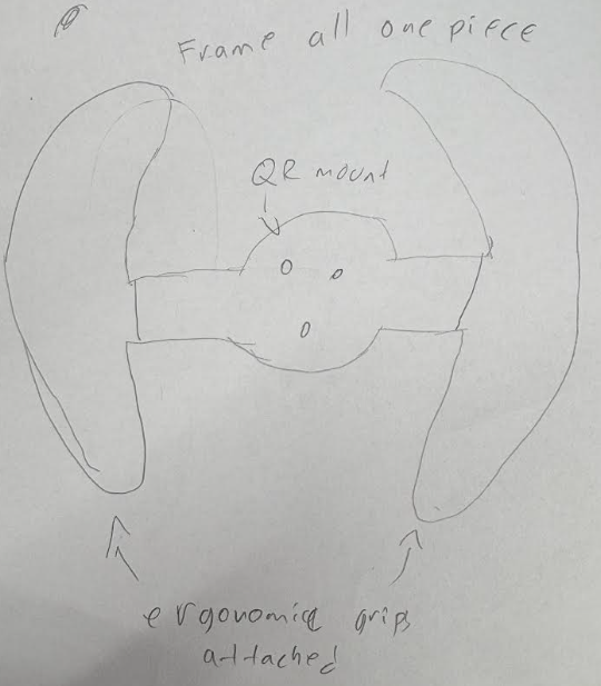
One-Piece Open Frame
4.55 / 5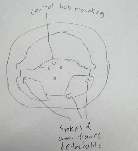
Modular Circular Frame
3.20 / 5I selected the closed frame for its strongest overall balance of stiffness, manufacturability, packaging, reliability, and mass efficiency while preserving a continuous Formula SAE-compliant perimeter.
Structural Optimization
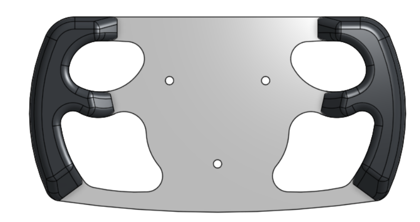
V1 / Baseline
V2 / Optimized
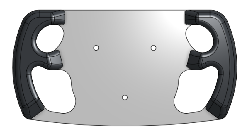
V1 → V2
I used V1 stress distributions to identify structurally inefficient material, then enlarged internal openings and reshaped transitions while preserving primary load paths. This stress-informed geometry iteration improved the governing simulated yield FOS from 2.16 to 2.28.
- Enlarged internal lightening cutouts
- Wider, smoother load-bearing transitions
- Material removed from low-value regions
- Primary structural load paths preserved
The revised geometry increased torsional stress while improving the governing bending cases. This was iterative geometry optimization guided by stress results.
Analysis & Validation
I modeled three assumed extreme driver load cases in ANSYS to identify governing stress regions and guide material removal. All V2 cases exceeded the study’s simulated yield FOS target of 2.
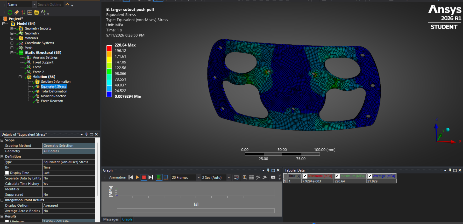
| Load case | Load | Max stress | Max deformation | Yield FOS | Result |
|---|---|---|---|---|---|
| Steering torque | 135 N·m | 55.95 MPa | 0.064 mm | 8.99 | PASS |
| Two-hand OOPGoverning case | 400 N | 220.64 MPa | 1.934 mm | 2.28 | PASS |
| One-hand OOP | 200 N | 209.26 MPa | 1.369 mm | 2.40 | PASS |
- ANSYS Mechanical
- Linear static structural
- 7075-T6 aluminum
- Distributed hand-contact loads
- Rigid quick-release approximation
- 2 mm global mesh
- 1 mm refinement at holes/cutouts
Static, linear-elastic model using nominal material properties. Fatigue, impact loading, manufacturing defects, grip stiffness, and a compliant quick-release interface were not modeled. Load values are study assumptions, not vehicle-specific measurements. The student-plan node limit constrained mesh refinement; mesh convergence remains future work.
Independent analytical check
- Force
- 200 N
- Lever arm
- 104 mm
- Bending stress
- ≈156 MPa
- Yield FOS
- ≈3.22
Simplified rectangular cantilever approximation used as an independent order-of-magnitude check on the FEA. It does not capture the full 2D load path or local stress concentrations.
Planned physical validation
Structural test
- Mount using the actual quick release or a representative rigid fixture.
- Apply controlled force at defined grip locations with a load cell / force gauge.
- Increase load in controlled increments; measure displacement with a dial indicator.
- Compare load–displacement stiffness with ANSYS predictions.
- Unload, check residual deformation, and inspect the plate, grips, quick release, and fasteners.
Acceptance checks
- No visible cracking
- No permanent deformation
- No fastener loosening
- Quick release remains functional
Driver evaluation
I will use a 1:1 prototype with drivers wearing racing gloves to evaluate finger clearance, wrist position, comfort, grip security, hand repositioning, and quick-release access, then iterate the grip geometry from feedback.
Manufacturing & Integration
Designed for fabrication
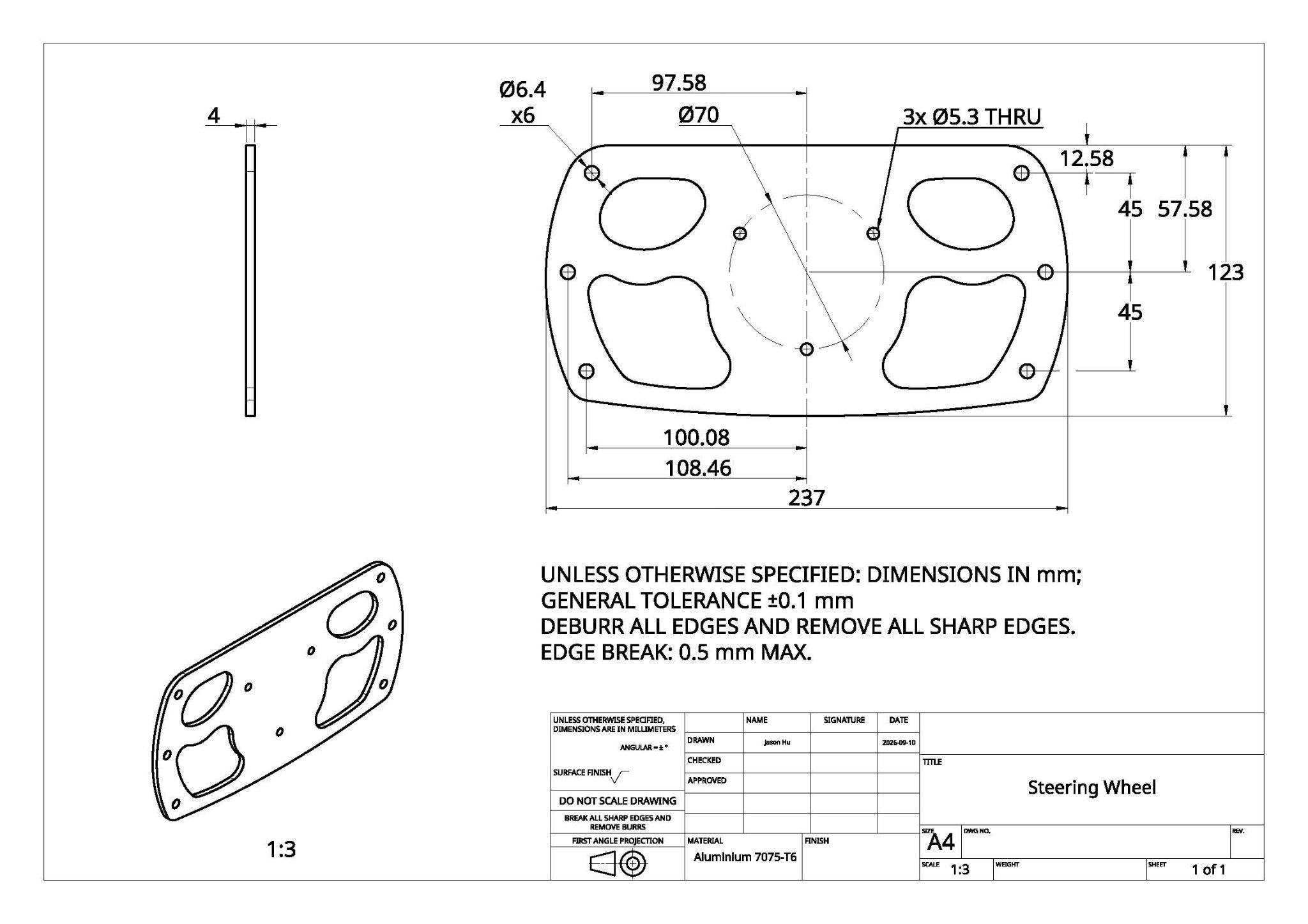
- 014 mm 7075-T6 plate
- 02Waterjet perimeter + large openings
- 03CNC precision holes
- 04Deburr / 0.5 mm edge break
- 05Dimensional inspection
- 06Optional anodizing
- Structural plate
- ~219 g
- TPU grips
- ~60 g
- Estimated assembled mass
- ~279 g
- Estimated component cost
- $85–145
Design estimates from the bill of materials; mass and cost have not been measured on a manufactured prototype.
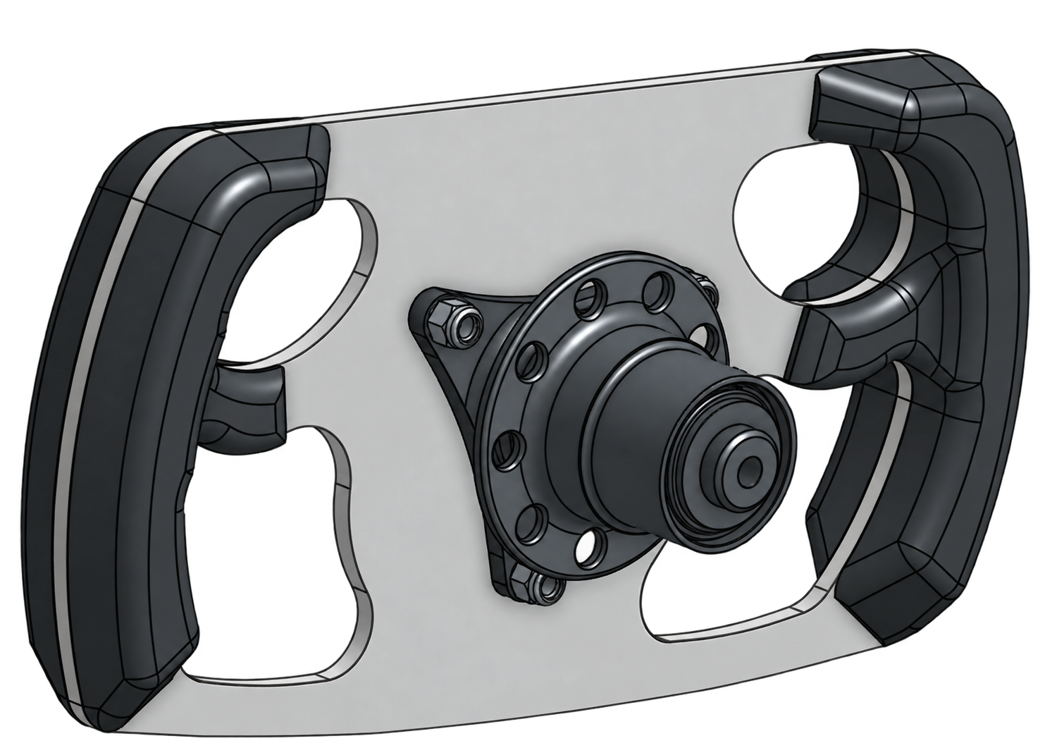
Strength + stiffness
The 7075-T6 aluminum plate carries primary steering loads. Its mostly planar architecture supports waterjet and CNC fabrication, assembly access, and inspection.
Comfort + friction
A compliant, higher-friction hand interface maintains gloved finger clearance. Replaceable printed grips allow driver-specific refinement without remanufacturing the aluminum frame, while keeping quick-release hardware accessible.
Outcome & Next Steps
From requirements to a manufacturable design
- 12.7% structural CAD mass removed
- Minimum simulated yield FOS of 2.28
- Three extreme load cases evaluated
- Manufacturing and inspection strategy defined
- Replaceable ergonomic grip architecture developed
- Physical validation plan established
This project combined requirements engineering, concept selection, CAD, first-principles analysis, iterative FEA, ergonomics, and manufacturing planning. I balanced mass reduction with structural margin, driver usability, rule compliance, fabrication, serviceability, and future validation.
Next iteration
- Replace assumed loads with vehicle-specific measured loads
- Improve the quick-release boundary condition
- Perform mesh convergence and higher-fidelity analysis
- Extend analysis to fatigue and cyclic loading
- Manufacture a prototype and correlate stiffness measurements with FEA
- Iterate TPU grips from driver feedback