The problem
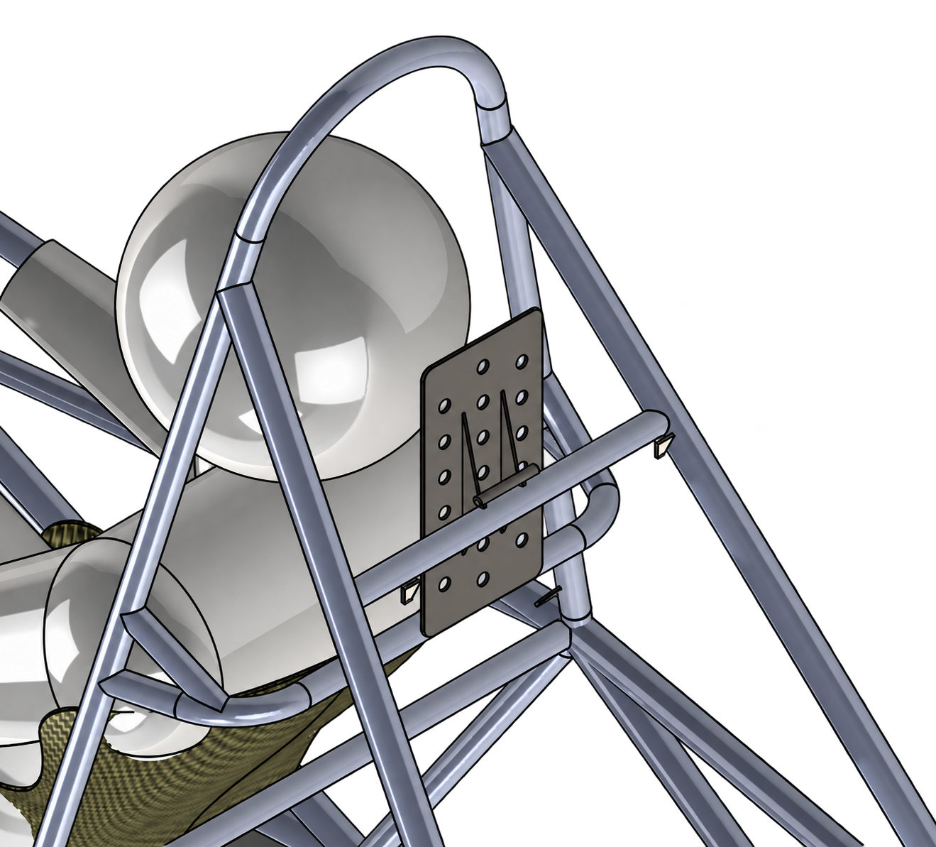
The headrest must transfer driver loads into a tightly packaged chassis while accommodating different helmet positions and remaining practical to fabricate. I studied the previous vehicle’s design, testing, driver feedback, and known failure and assembly issues to identify opportunities for structural efficiency and easier manufacturing. The challenge is to improve the complete system: backplate, mounts, chassis tube, and driver contact geometry.
My contribution
- Translated Formula SAE rules and prior vehicle evidence into dimensional, positioning, structural-load, and driver-safety requirements.
- Evaluated mounting architectures, materials, and manufacturing processes before refining the backplate, tabs, and chassis interface.
- Combined free-body diagrams, hand calculations, FEA, and topology/geometry optimization to guide mass removal while preserving structural load paths and stiffness.
- Used driver feedback and human geometry in CAD to evaluate helmet position, posture, clearances, and accommodation across approximately a 5th-percentile female to a 95th-percentile male.
- Collaborated with the chassis subteam on mounting-tube placement and revised interface geometry as the surrounding vehicle structure evolved.
- Designed for manufacturing and assembly, with continued ownership planned through fabrication, chassis integration, load testing, and driver fit validation.
Requirements that shape the design
Design development
Research & requirements
Reviewed the prior headrest, vehicle architecture, testing, and driver feedback. Converted those lessons and Formula SAE rules into requirements that guide concept comparison.
Concept development
Compared mounting architectures and material/process combinations for strength, stiffness, density, weldability, availability, and cost. Coordinated concept selection with chassis geometry and driver packaging.
Analysis & optimization
Used free-body diagrams and hand calculations to establish load paths, then FEA and topology/geometry optimization to refine thicknesses, tabs, reinforcement, and hole/dimple concepts. Evaluated each change against mass, stiffness, stress concentration, and manufacturing constraints.
Human-centered integration
Simulated driver packaging in CAD using human and helmet geometry. Evaluated headrest position, posture, contact geometry, and clearances across the target driver population, incorporating driver feedback before fabrication.
Design for manufacturing
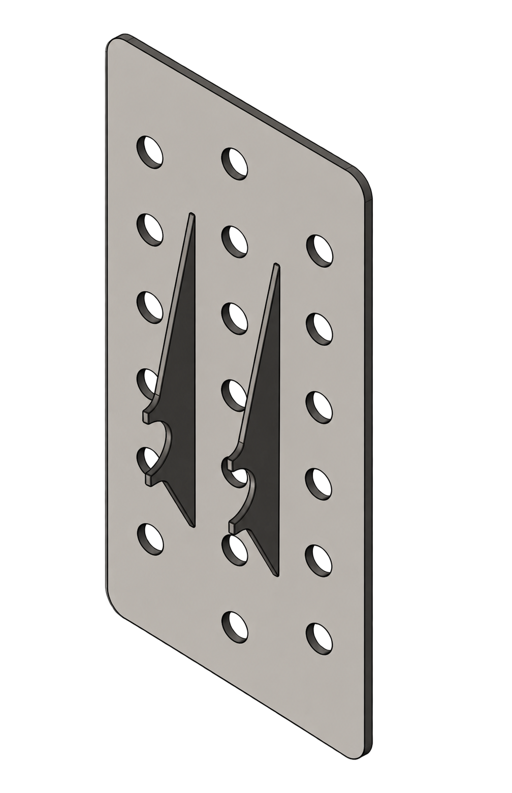
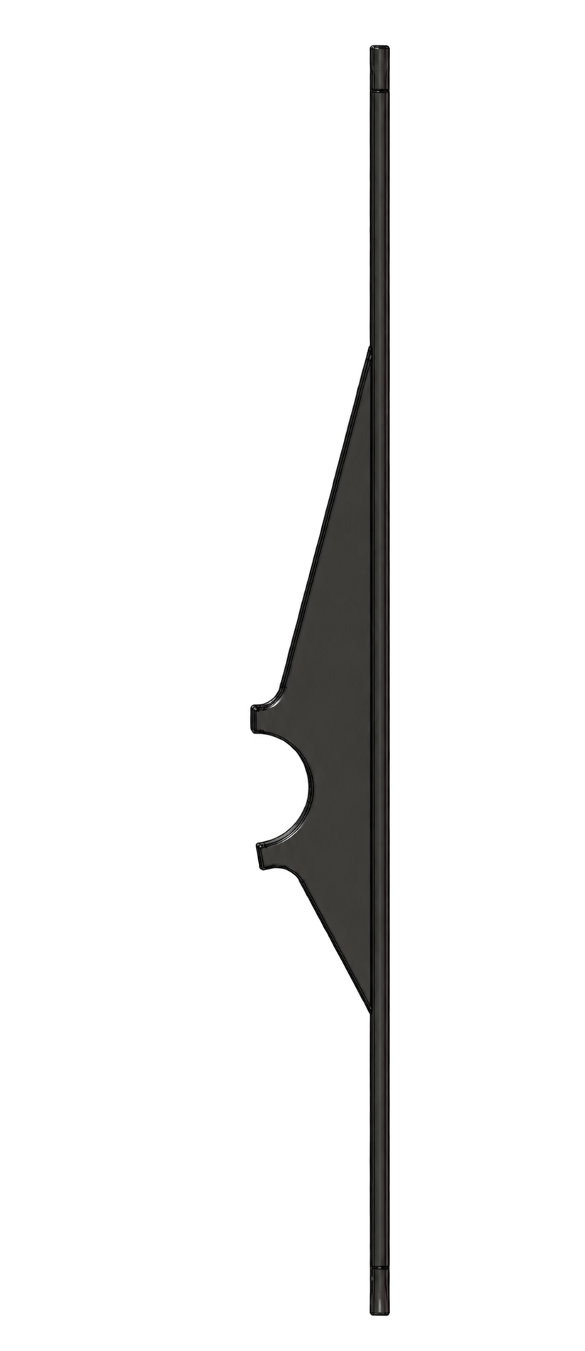
Refined the backplate and chassis interfaces around laser cutting, forming, weld access, and assembly. Revised tab geometry to simplify fabrication while retaining the intended structural load path.
Manufacturing & validation — upcoming
Follow the design into fabrication and chassis assembly, resolve tolerance issues, and compare physical load and driver-fit tests with the analytical predictions. Use findings to drive final design iterations.
Engineering decisions
Load paths before lightweighting. I evaluate the backplate, tabs, welds, and chassis interface as a coupled structure. Hand calculations and free-body diagrams establish how rearward and lateral/vertical loading create bending and reactions; FEA informs local stress and stiffness decisions. Topology and geometry studies help identify low-value material, with removal judged against structural reliability and manufacturing feasibility.
Geometry must earn its complexity. Thickness, reinforcement, and hole/dimple geometry can change mass, sheet-metal behavior, and local stiffness simultaneously. I evaluate stress concentrations, tab bending, weld geometry, and fabrication access together, retaining lightweighting features only when their structural and manufacturing tradeoffs justify them.
Mounting location is a system decision. With the chassis subteam, I evaluated tube placement against helmet position, cockpit packaging, weldability, and chassis geometry. Moving the interface changes bending moments, tab length, load transfer, and component mass. I iterated the mounting architecture across subsystem boundaries as the chassis evolved.
Build & integration
I researched backplate, tab, and lightweighting processes and developed the CAD around realistic team manufacturing capabilities. Laser-cut profiles, sheet forming/dimple dies, weld accessibility, and assembly sequence influence material and dimensional choices alongside structural analysis.
The manufacturing phase is upcoming. I will oversee fabrication with the manufacturing team during cutting, forming, welding, and assembly, resolve tolerance or process issues as they appear, and integrate the finished headrest into the chassis.
Validation
Design decisions are currently informed by calculations, FEA, CAD packaging, and prior vehicle testing. Physical testing of this design and final compliance verification remain upcoming.
I will conduct structural/load testing and compare measured behavior with hand calculations and FEA predictions. Driver fit checks across different body sizes will evaluate helmet contact, posture, clearances, and usability. Test results and driver feedback will guide final changes before vehicle validation.
Outcome
The current work establishes an analysis-driven headrest design and chassis integration approach, with manufacturing and physical validation still ahead. My contribution connects requirements, structural optimization, human-centered packaging, and DFMA in one safety-critical subsystem, with ownership extending into the build and test phases.
Next iteration
Oversee final component fabrication and chassis assembly, resolve manufacturing and tolerance issues, then complete structural load tests and driver fit validation. Compare results against calculations and simulations, refine the design from test evidence and driver feedback, and document the final configuration before vehicle validation.