The problem
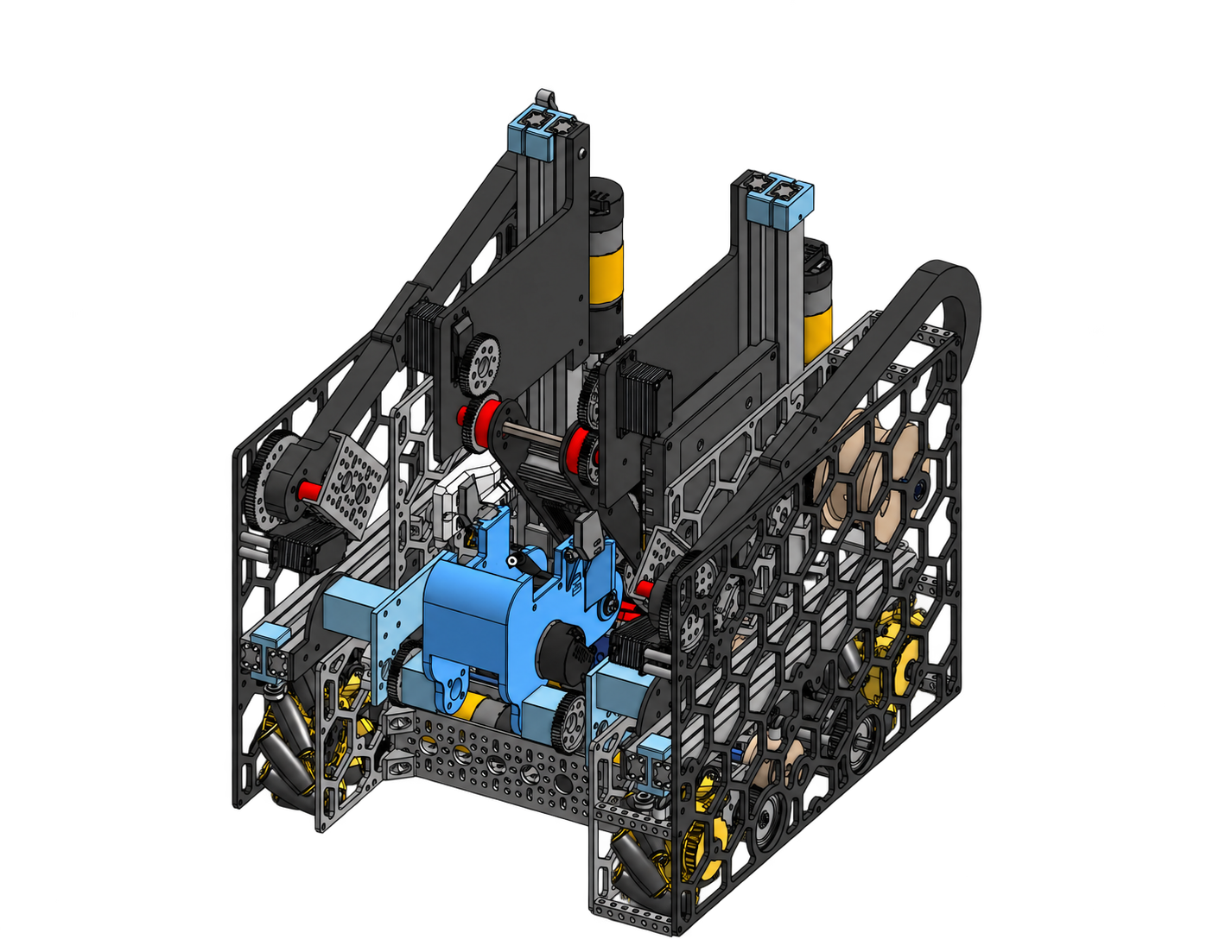
Each season demanded a new way to acquire and score game pieces within a constrained robot envelope. Reach, stability, maneuverability, and service access competed for the same space. The challenge was to make drivetrain, manipulator, localization, electronics, and software behave as one reliable system under competition schedules.
My contribution
- Led mechanical architecture and hardware development across a 15-member team as Captain & Hardware Lead.
- Owned the three robot architectures below, including drivetrain, manipulators, and spring-loaded localization hardware.
- Used parametric Onshape CAD and engineering analysis to guide motion, stability, structural support, and subsystem interfaces.
- Directed fabrication, assembly, integration, and performance validation alongside electrical and software members.
- Trained younger members and published reusable parametric designs with more than 200 downloads.
Three seasons. Three mechanical architectures.
Precision manipulation → multi-axis reach → independent targeting
Stability at full extension.
Challenge — Move game pieces rapidly to an inclined scoring surface without sacrificing stability, precision, or chassis compactness.
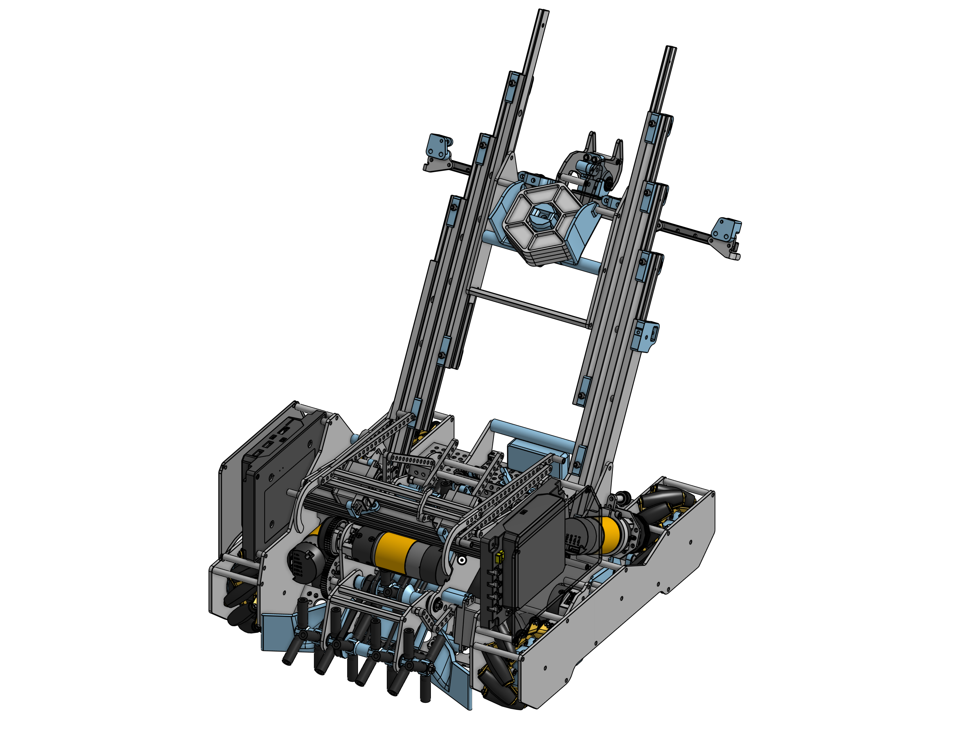
- Dual inclined slides
- Powered roller intake
- Compact drivetrain / CG-managed layout
Measured on integrated competition hardware during repeated testing.
Architecture & rationale
I designed paired linear slides aligned with the scoring angle, using parallel support to resist torsional motion during rapid extension. As the manipulator shifted mass beyond the drivetrain footprint, I used center-of-gravity and tipping calculations to guide component placement and counterbalancing. A powered roller intake controlled acquisition, alignment, and transfer. I carried the mechanism from CAD through fabrication, integration, and iterative testing, validating both slide stability and the complete intake-to-score sequence.
Requirements that shape the design
Design development
Translate the game into architecture
Define scoring functions, deployment constraints, and subsystem interfaces. Compare concepts against available volume, team capabilities, and the competition schedule.
Develop and articulate the CAD
Build parametric Onshape assemblies and evaluate the full operating range. Use motion checks and analysis to resolve conflicts before committing to fabrication.
Realize the complete system
Plan component selection and purchasing, then integrate fabricated mechanisms with drivetrain, actuators, sensors, and electrical hardware.
Close the loop with evidence
Reproduce failures, identify the controlling interface, revise the design, and retest. Carry match experience into the next architecture.
Engineering decisions
Design the drivetrain around the deployed robot
I coordinated wheel and motor placement, frame rigidity, mass distribution, and maintenance access with the manipulator and tracking-wheel interfaces. The drivetrain had to remain maneuverable while supporting changing loads and reliable localization; optimizing it in isolation would miss those interactions.
Support the load without consuming the envelope
End-effector loads transfer through the slides into the frame. I evaluated support, stiffness, deflection, and tolerance stack-up together, balancing structural behavior against mass and available volume. Mounting alignment and accumulated tolerances can turn a freely moving component into a binding assembly.
Choose improvements the team can validate
Near competition, a performance gain must justify fabrication effort, integration risk, and remaining test time. I weighed proposed changes against serviceability and the team’s ability to build, diagnose, and repair the resulting hardware.
Spring-loaded localization hardware
I designed compliant tracking-wheel odometry to maintain field contact through robot motion and surface irregularities. I evaluated spring behavior and range of motion, managing mounting alignment, backlash, and clearance. After manufacturing and testing the mechanism, I revised it around slip and inconsistent contact, coordinating the mechanical behavior with the software team’s localization requirements.
Build & integration
I translated CAD into fabricated parts and assemblies using team-accessible processes and purchased hardware. Hands-on fit-up exposed constraints around mating interfaces, fastener access, assembly sequence, and adjustment; I revised geometry and alignment where needed.
With electrical and software members, I integrated actuator mounts, sensor placement, and wiring access. I coordinated purchasing and distributed mechanical work so subsystem builds converged into a serviceable competition robot.
Validation
I tested repeated cycles and representative mechanism loads, with impact checks where applicable. Integrated operation exposed tracking-wheel slip, inconsistent contact, slide binding, backlash, and excessive deflection that isolated bench checks could miss.
I reproduced failures, inspected the controlling interfaces, and retested revisions under competition-like operation. The Robot Evolution measurements above capture the resulting motion and scoring performance; match experience also informed reliability and repair decisions.
Outcome
Three distinct mechanical architectures reached functioning competition hardware, combining mechanism design with robot-level packaging and measured performance. I led that work across a 15-member team and shared reusable designs beyond it through more than 200 open-source downloads.
Next iteration
Document representative robot configurations and mechanism revisions with CAD and build records, linking each observed failure to its design change and subsequent test. Carry those integration and validation lessons into future hardware development.